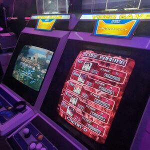
I first tried this game when I got my Naomi NetDIMM setup and it’s a quirky yet addictive game. It’s playable on a joystick setup, but since it’s got a dedicated cabinet with extremely oversized buttons, I figured why not try and go down this avenue without having to purchase the whole cabinet?
The arcade cab looks like this – as you can see the buttons are extremely oversized to the point they had to make a different control panel to accommodate the size of the buttons

I planned to use the Sega Blast City, which meant I needed some sort of control panel.
I came across this thread on Arcade Projects who seemed to have a panel that had the same buttons as the original albeit smaller, but it fit the standard Sega control panel, so I reached out to Alberto to organise a panel for me.
During the time, I also reached out to CQB Arcade to see if he was able to source out the required buttons for the panel. I figured it was better to support the local business.
The following was ordered
2x OBSAX-C30UM-W-1FLED-W-12V (start buttons)
8x OBSAX-C30UK-W-1FLED-W-12V (directional buttons)
4x OBSAX-C45UM-W-1FLED-W-12V (A and B buttons)
Fast forward to a few days ago, all the buttons arrived with a nice little extra items, props to CQB as my kids enjoyed the extras 
![[IMG]](https://i.imgur.com/qpK3PXBh.jpg)
![[IMG]](https://i.imgur.com/FTfG5c1h.jpg)
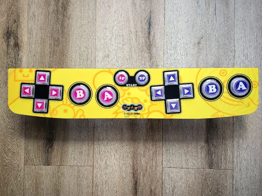
Each button can be disassembled so artwork can be placed under the top cover
![[IMG]](https://i.imgur.com/7XvfGMuh.jpg)
Once all installed, it should look like below. This will be the closest I can get to the original without having the dedicated cab. The main difference is the size of the buttons, the original directional buttons are 45mm vs the 30mm on this panel and the size of the A and B buttons 60mm on the original vs 45mm for this panel
Next was to start the wiring harness. Since this will be going to the Blast City and that cab doesn’t have a dedicated JVS I/O, I thought something like this would be a decent way to rig it up whilst having the ability to use the existing connector for P1 and P2 on the blast city.
![[IMG]](https://i.imgur.com/fnVF6Feh.png)
I got shared the wiring schematic of the game by Lemony Vengence and Tak and based on the information from the schematic, I ended up with this schematic (colours are my chosen colours based on wire I have)
For the directional inputs (same as a standard sega joystick)
![[IMG]](https://i.imgur.com/JZ0MLS1h.png)
For the LEDs
![[IMG]](https://i.imgur.com/gzx1p7ih.png)
Some stats for the panel harness –
- 14x JST NH 4 Way
- 112x Crimp connectors
- 56x wires totaling around 4m give or take
- 4x different connectors (2x TE Amp Up 12 way, 1x TE Amp Up 8 way, 1x JST YL 12 Way)
What a mess of spaghetti!!
![[IMG]](https://i.imgur.com/49kLkAAh.jpg)
This is where the multi meter does wonders! Because of my colour coding, I had accidentally wired up 12v into an input, that would’ve been interesting to say the least 
After a few hours of looking at the schematics, crimping, cutting, testing for continuity, here’s the control panel in its final form – cable ties ftw!!!!
![[IMG]](https://i.imgur.com/qO20b5Qh.jpg)
Next up, I’ll need to make another harness from the JVS I/O to these connectors.