As previously mentioned, I had planned to wire harness with a JAMMA edge like this:
![[IMG]](https://i.imgur.com/fnVF6Feh.png)
@LemonyVengeance gave me the idea of bypassing the JAMMA edge and just wire it directly to the Blast City I/O.
Due to the sheer amount of wire I needed, I figured it would be cheaper to bastardise an old original Blast City harness that I got for 30 dollars (not the one the Sega 001 loom, but an original Blast City one). I also had a whole heap of JVS power harnesses laying around and other bits and bobs I could use.
I removed pins that I didn’t require from the harness – I only needed, P1 and P2 Up, Down, Left, Right, Start, B1 and B2, test, service, coin, coin meter.
![[IMG]](https://i.imgur.com/G6n21E6h.jpg)
I know it’s not a pretty sight to hack up original harnesses, especially those Hirose JAMMA edge, but I promise, this is for the greater good

![[IMG]](https://i.imgur.com/7DwHCfAh.jpg)
With the new harness, meant new colour coding, so I updated the spreadsheet with the colours. I get crap for having spreadsheets from family and friends all the time, but I’m telling you, if I didn’t have this spreadsheet, I would’ve had heaps of issues.
My updated schematics
![[IMG]](https://i.imgur.com/reu5UJRh.png)
![[IMG]](https://i.imgur.com/guPGEeUh.png)
The main wiring (P1 and P2 buttons – no lamp/power) was completed after a solid couple of hours, was checked and double checked for continuity to make sure everything was in its proper position
![[IMG]](https://i.imgur.com/w6BpLnnh.jpg)
![[IMG]](https://i.imgur.com/8O4w5HLh.jpg)
I started working on the lamp and power harness but I didn’t realise that the connector for that was 20 way! I only had a 26 way! FMD *face palm*. I ordered a 20 way, but I was determined to get this done so I hacked up the 26 way and turned it into a 20 way but cutting the last holes and the tab on the connector as the JST RA is keyed.
![[IMG]](https://i.imgur.com/YRLKfcOh.jpg)
The harness is now complete! Also added the stereo RCA’s. This OG harness has essentially been turned into a Sega 001 loom plus the requirements for LEDs to light up according to the game code.
![[IMG]](https://i.imgur.com/y81gBvYh.jpg)
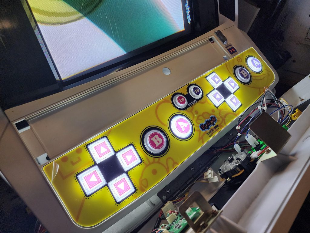
Here’s the big test!
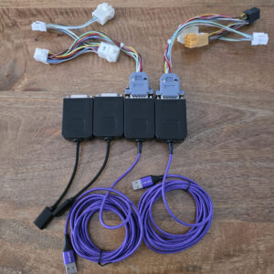
All wired up to a Sega type 3 JVS I/O if LED buttons are to be used, otherwise, I could’ve just used the normal Sega JAMMA to JVS I/O or the I/O found in a NNC (Sega type 1 JVS)
![[IMG]](https://i.imgur.com/7KNrHl6h.jpg)
The first power on was the most nerve wracking as there’s always doubt with these things, I’m always scared I wire 12v up where 5v goes, it also doesn’t help Sega doesn’t use “standard” colours like those found in an ATX PSU ie. 5v = red, 12v = yellow. Sega uses Yellow for 5v and red for 12v! You can see where people would mix this up and fry pcbs.
Needless to say, I was VERY happy when I turned the cab on, loaded the game and there was no smoke and the buttons and LEDs worked!
Quick video of it working