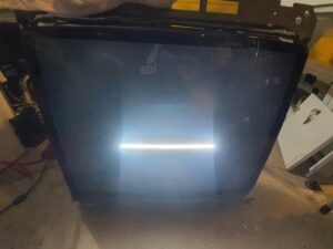
After finally admitting defeat the other day, I started thinking about how to install the game using JAMMA. When I purchased a Point Blank PCB, I was also given a Point Blank wiring harness with the JAMMA edge connector so I thought I’d use that and retro fit it into the cabinet somehow.
As I started tracing out wires, I came across this little pcb on the harness which had what seemed to be video related wires connected to it (r g b sync and vgnd). It’s a bare basic pcb with 3x 100 ohm resistors on the rgb lines, needless to say, it had official Namco silkscreen on it, so I assumed it was “legit”
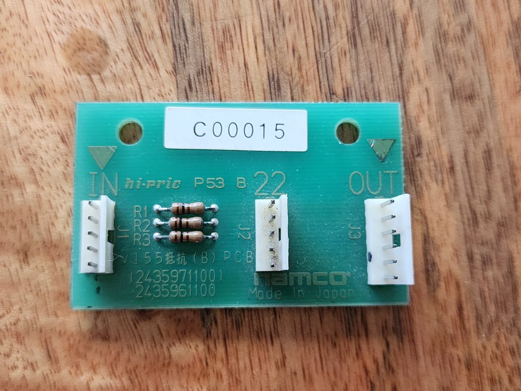
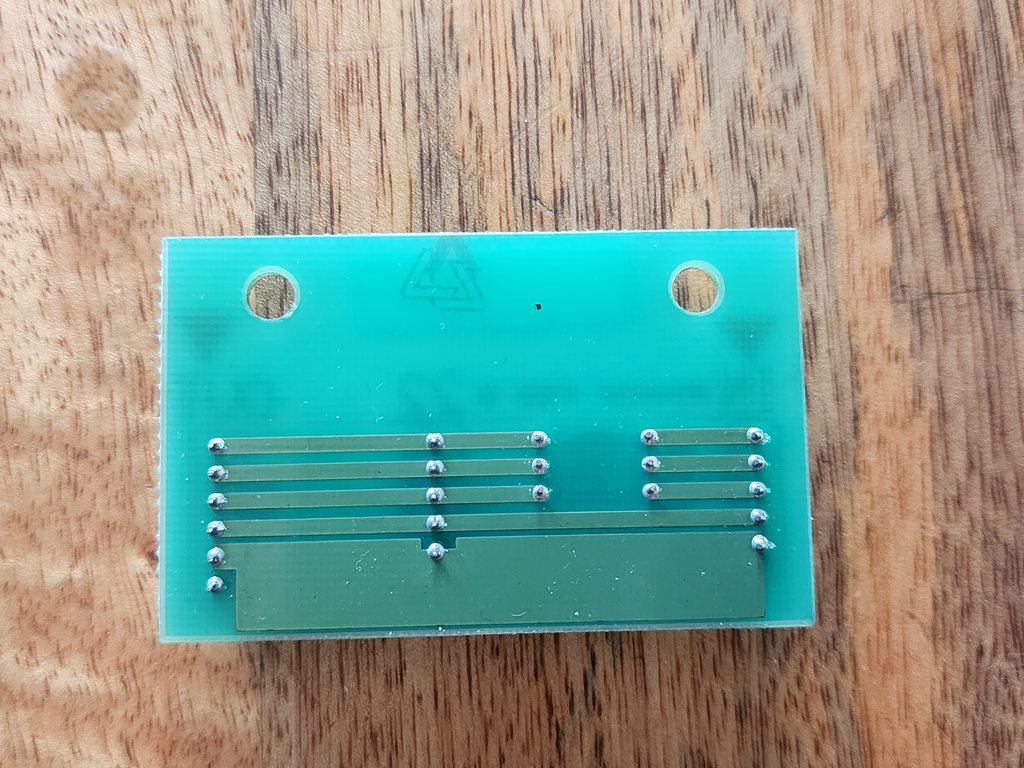
So I figured… What the hell? Why don’t I wire it up and see what happens. What else have I got to lose at this point?
I rigged up the “IN” header from the monitor/chassis and “OUT” header to the Namco emi filter board.
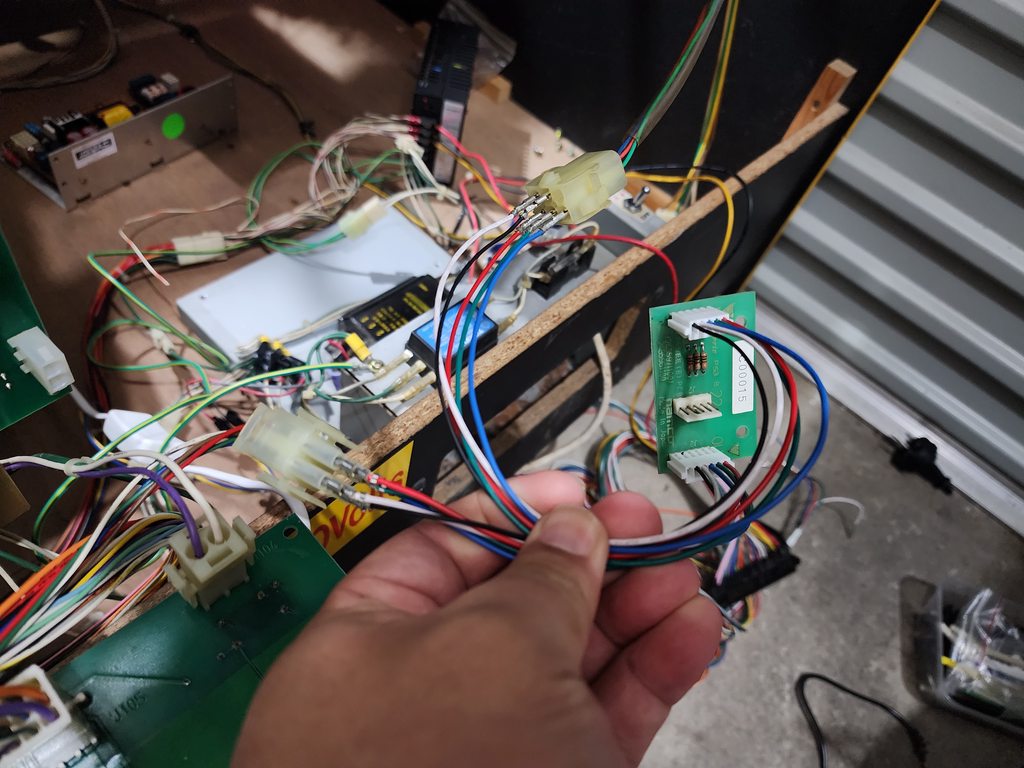
When I turned the cab on, I was expecting the same issue as I’ve been receiving, but to my absolute shock, I was greeted with a stable image!!
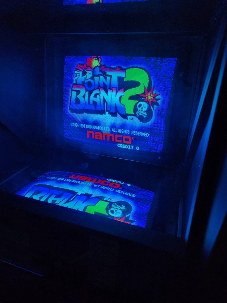
Monitor needs calibration but at least I’m now getting perfect sync!
After looking at my reference pics, it seems the old tube/chassis combo I had was a TOEI TC-A292N 3 and the one I have now is just a TC-A292. I’m assuming the N 3 model was updated so it didn’t need the inline resistor pcb? I have no idea. Someone much smarter than me will have to explain as I can only assume that the RGB lines out of the EMI filter board is sending out a higher voltage than what a regular jamma monitor is expecting because the issue only occurs when the EMI filter board is attached.
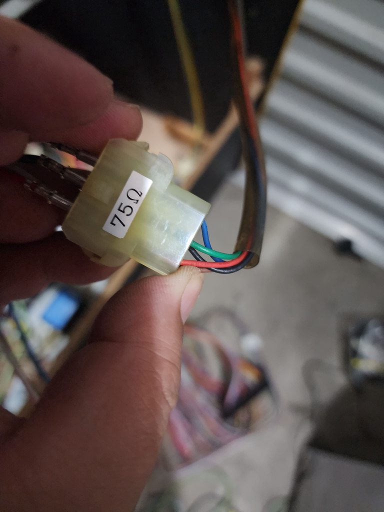
I have a 75 ohm sticker on my current monitor connector and I’m not sure if the previous monitor also had this 75 ohm on the sticker.
Lesson of the day folks: don’t worry about screen burn and make sure you test before selling the cab you installed the burnt monitor  .
.
I was so fixated on having a “burn free” tube and when I swapped tubes, I didn’t bother swapping the chassis as I initially thought they were the same chassis. I also didn’t do any tests to confirm this burn free monitor would work in the Point Blank cabinet because the PSU was sent to be serviced and couldn’t test. I made a terrible assumption that because it worked on my Time Crisis cab, it should also work on this cab – here I am thinking it’s a simple plug and play – it’s only two connectors! How wrong was I?!?
Now that the sync issue is finally out of the way, I can now focus again on a few of the aesthetic things.
The other day, I got delivery of NOS JPN artwork as I didn’t really like the one I originally purchased. The OEM cutouts on this new set will make installation much easier.
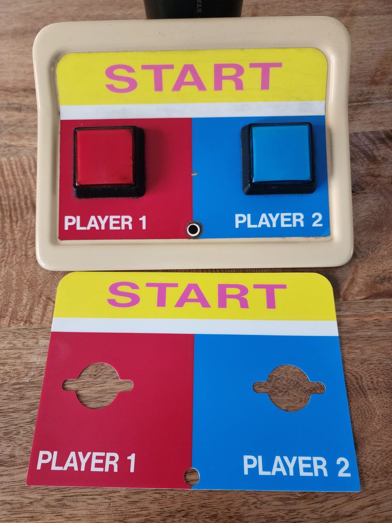
As we are going for the original gunbullet control panel art, here’s the comparison of the two I have
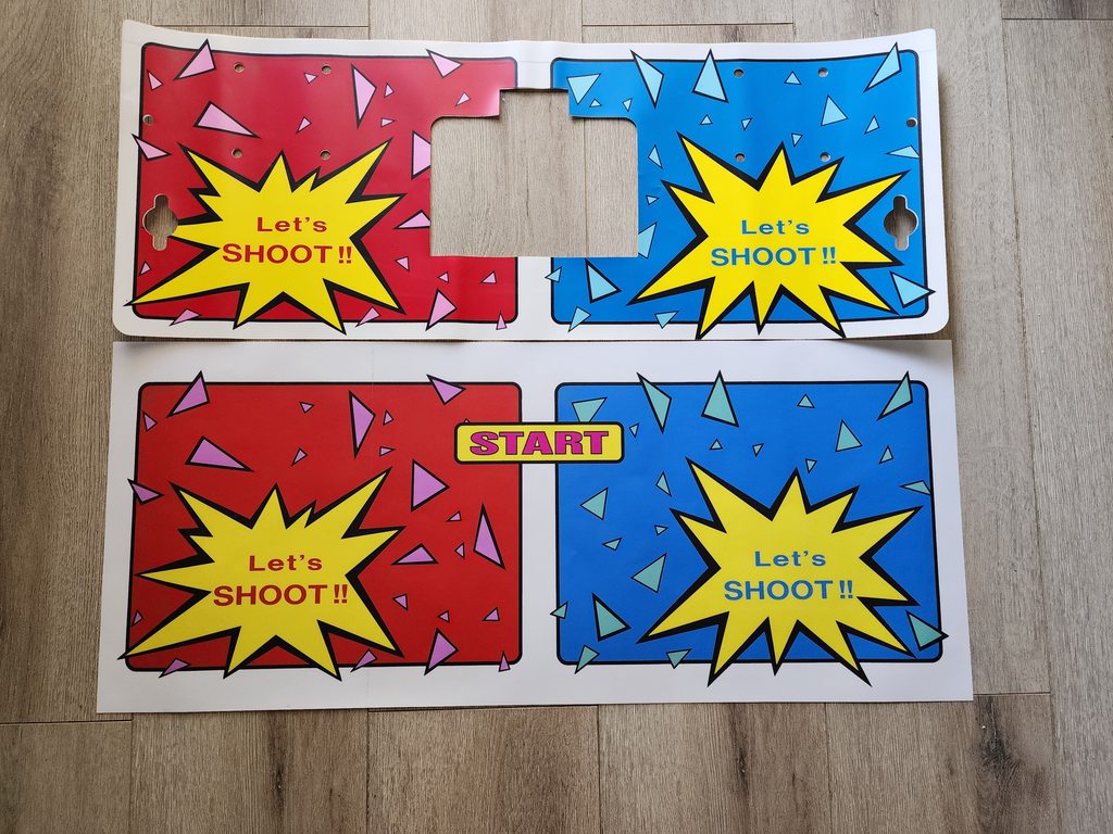
The art itself is very good and pretty close to the original, the major differences are obviously the cutouts and the texture. Colour reproduction is pretty close
The repro I got is highly textured vs the NOS one being smooth (I guess that could be fixed up by using a smoot matt finish vinyl). The material on the NOS decal feels slightly thicker too

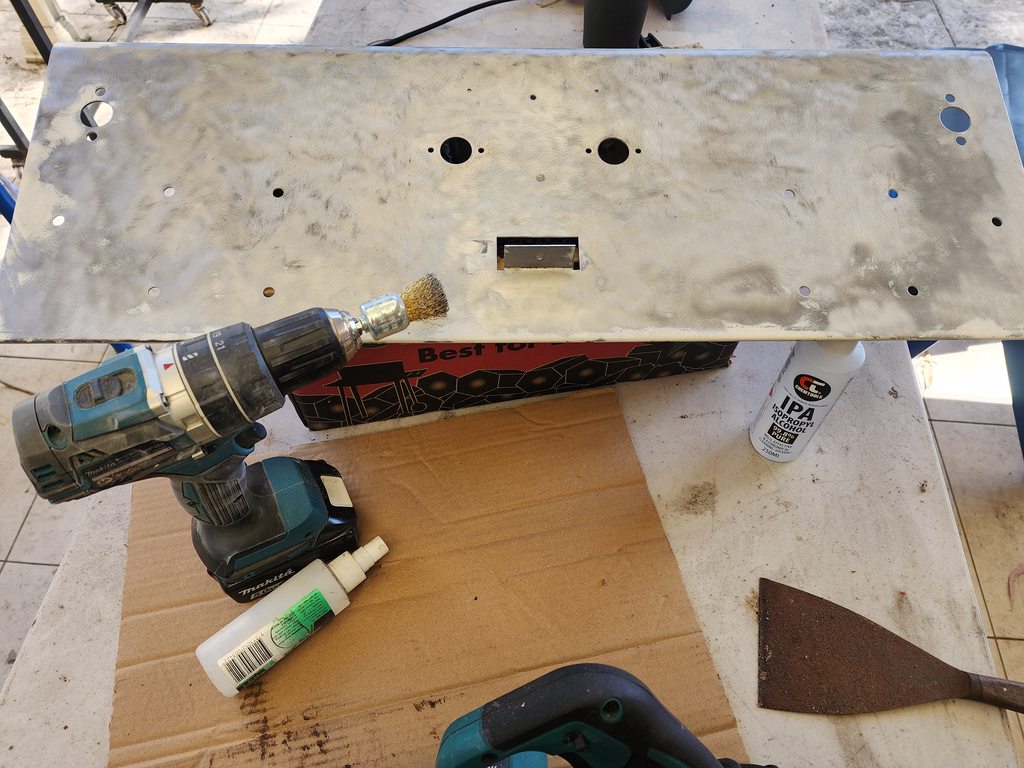
I’ve managed to get the panel to bare metal and will need to do the other side to get the rust out and then prep for primer
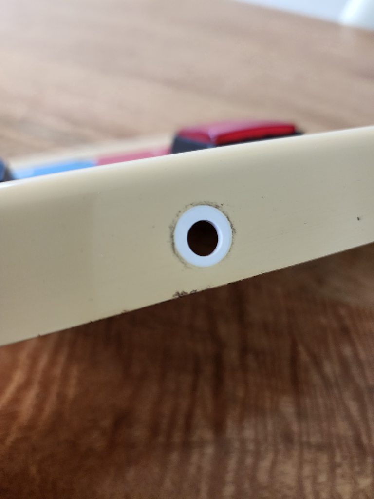
The start button decal also came through and whilst it doesn’t look all that bad, it’s actually pretty good if I’m honest, but I figured I’m already paint the control panel, might as well do the start button section white like what it’s supposed to be.
Next steps are:
- Calibrate monitor
- Make proper connectors for the inline resistor pcb so it connects to the EMI filter board and Chassis properly
- Prime and Paint control panel and start button plastic
- Install NOS decals
- Remove test PSU and respective wiring ie. JAMMA edge
- Re-install control panel with guns
- Get some high scores in game!
